
JOINT RADAR - COMMUNICATIONS SYSTEMS
On this page, we show our proposed DFRC strategies for joint radar-communications (a collaboration with Tsinghua University). Specifically, we demonstrate five different DFRC systems: spatial modulation-based communication-radar (SpaCoR), multi-carrier agile joint radar communication (MAJoRCom) FMCW-based joint radar-communications system (FRaC). Full-duplex DFRC system and Single Antenna Joint Radar and Communication (SAJRC). The SpaCoR system allocates antenna elements among the radar and communications subsystems based on the transmitted message, thus achieving increased communication rates by embedding additional data bits in the antenna selection. The MAJoRCom system exploits the inherent spatial and spectral randomness of carrier agile phased array radar to convey digital messages in the form of index modulation. The FRaC system embeds the information bits into the spatial and frequency index modulation utilizing the low-cost mmWave radar boards. The Full-duplex DFRC system send messages to each other and detect simultaneously while The SAJRC system using single antenna while decoding different overlapped communication and radar signals at the same frequency and same time using a recover sparse vector under Gaussian mixture model interference using sparse Bayesian learning. These demos were presented at ICASSP 2019, ICASSP 2020, ICASSP 2021, ICASSP 2022 and ICASSP 2023, ICASSP 2021, respectively.
SpaCoR Demo
Hardware Details:
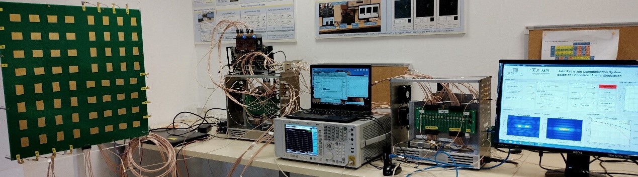
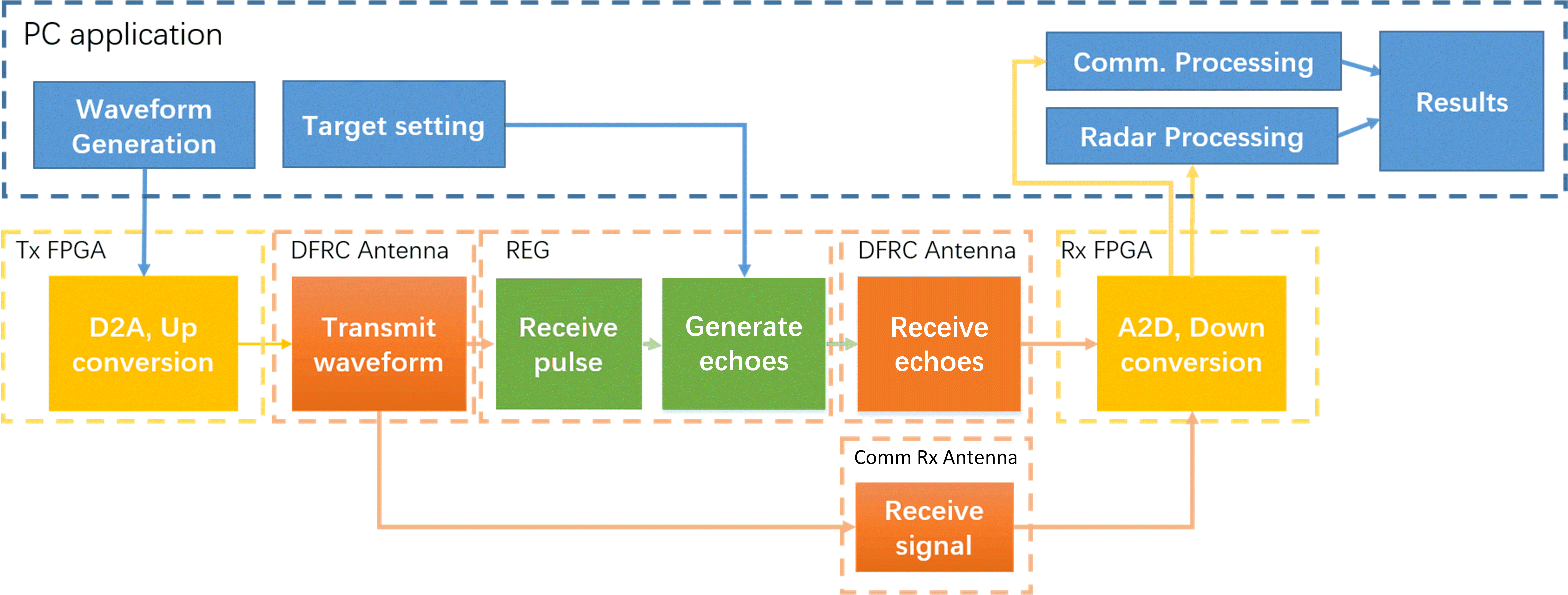
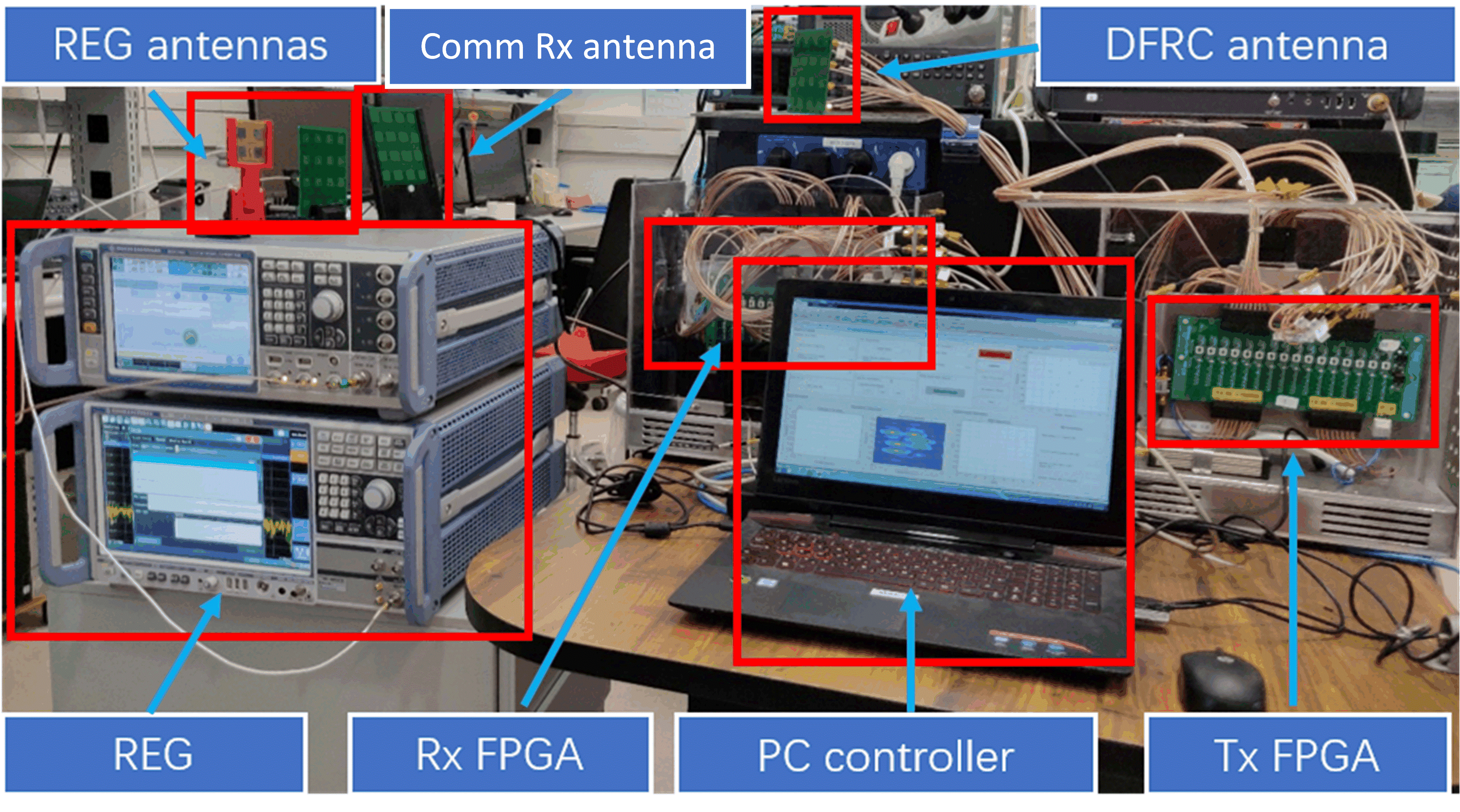
Our demo consists of: 1) PC server, which provides graphical user interface (GUI) for setting the DFRC parameters, generates the waveforms, and processes the received signals; 2) two-dimensional digital antenna array with 64 elements, which enables to independently control each element; 3) pair of FPGA boards interfacing the DFRC transmitted and received signals, respectively, between the PC and the antenna; and 4) radar echo generator (REG) which receives the transmitted waveform and generates the reflected echoes.
Through the GUI, the parameters of the radar and communication subsystems, as well as those of the experimental setup, are configured. Once the parameters are set and an experiment is launched, the joint radar and communications (JRC) waveform is generated by the PC application. Then, the JRC waveform is transferred to the DFRC transmit FPGA in which it is converted into analog, up-converted to passband, and forwarded to the DFRC antenna array for transmission. The transmitted waveform is received by the REG, which in response transmits echoes simulating the presence of radar targets, as well as by a receive antenna, which is connected to the receive FPGA. The received radar echoes at the DFRC antenna and the received communications signal are down-converted, digitized and then sent to the PC server. The digitized signals are processed by the PC application, which in turn recovers the radar targets and the communication messages.
Results:
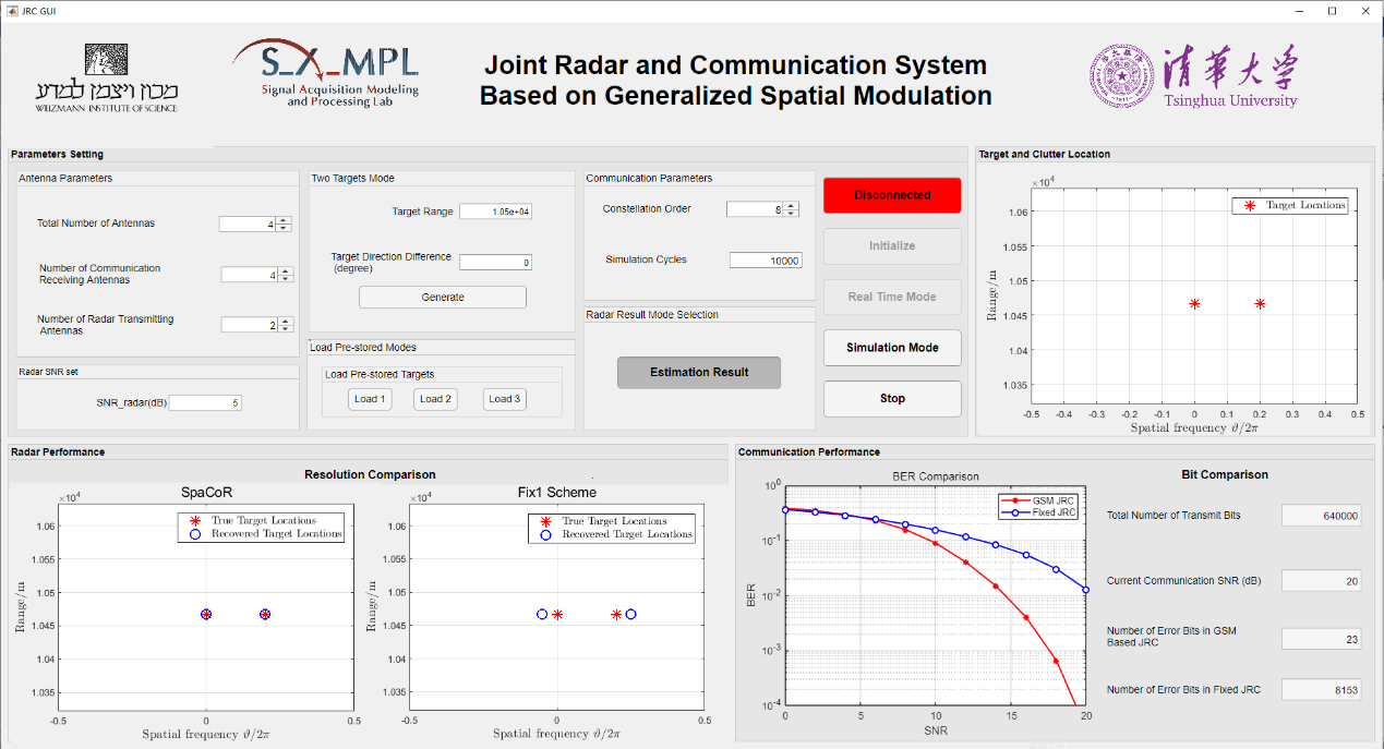
A screenshot of the GUI is shown as below. In order to simulate the DFRC system using the hardware prototype, one must first select the system configuration. The configurable properties of the system include radar parameters, communication parameters, and DFRC platform parameters. For the radar subsystem, the GUI allows to set the SNR of the radar echoes, i.e., the amount of noise added to the received waveforms in software, as well as the selection of the simulated target scenario mode. For the communications subsystem, one can specify the constellation order and the number of GSM symbols used. For the platform parameters, the GUI allows configuring the number of elements used in the antenna array. It is observed that the proposed JRC system can obtain higher resolution in radar subsystem and get a better communication performance compared with the fixed allocation scheme.
MAJoRCom Demo
Hardware Details:
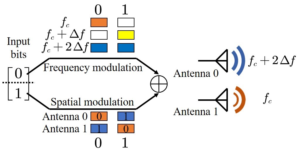
The hardware prototype of MAJoRCom is shown in the above figure. In this demo, the two-dimensional digital antenna array has 16 elements, which is divided into 8 transmit elements and 8 receive elements. The communication information is embedded in the election of frequencies and the allocation among antennas, as shown in the following figure. The function of the other hardware components is similar to that described in SpaCoR demo.
Results:
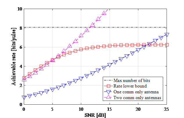
In this experiment, we evaluate the communication performance of MAJoRCom system as shown in the following figure. It is observed that MAJoRCom is comparable with using dedicated communication antennas without affecting radar. Please refer to the demo movie and reference papers for more details.
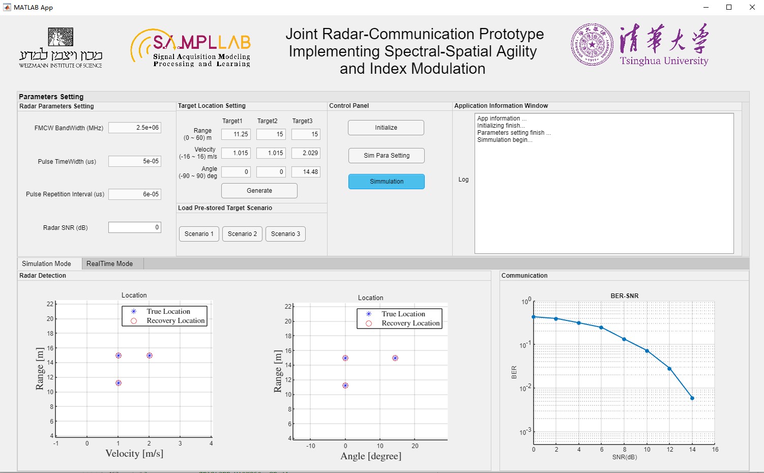
FRaC Demo
Hardware Details:
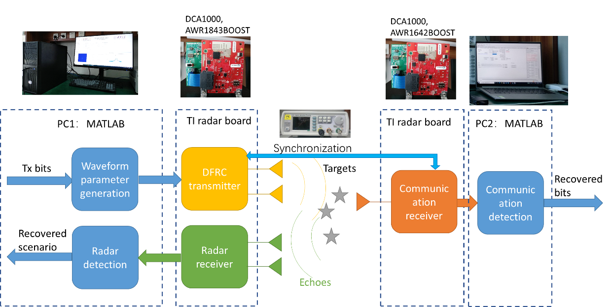
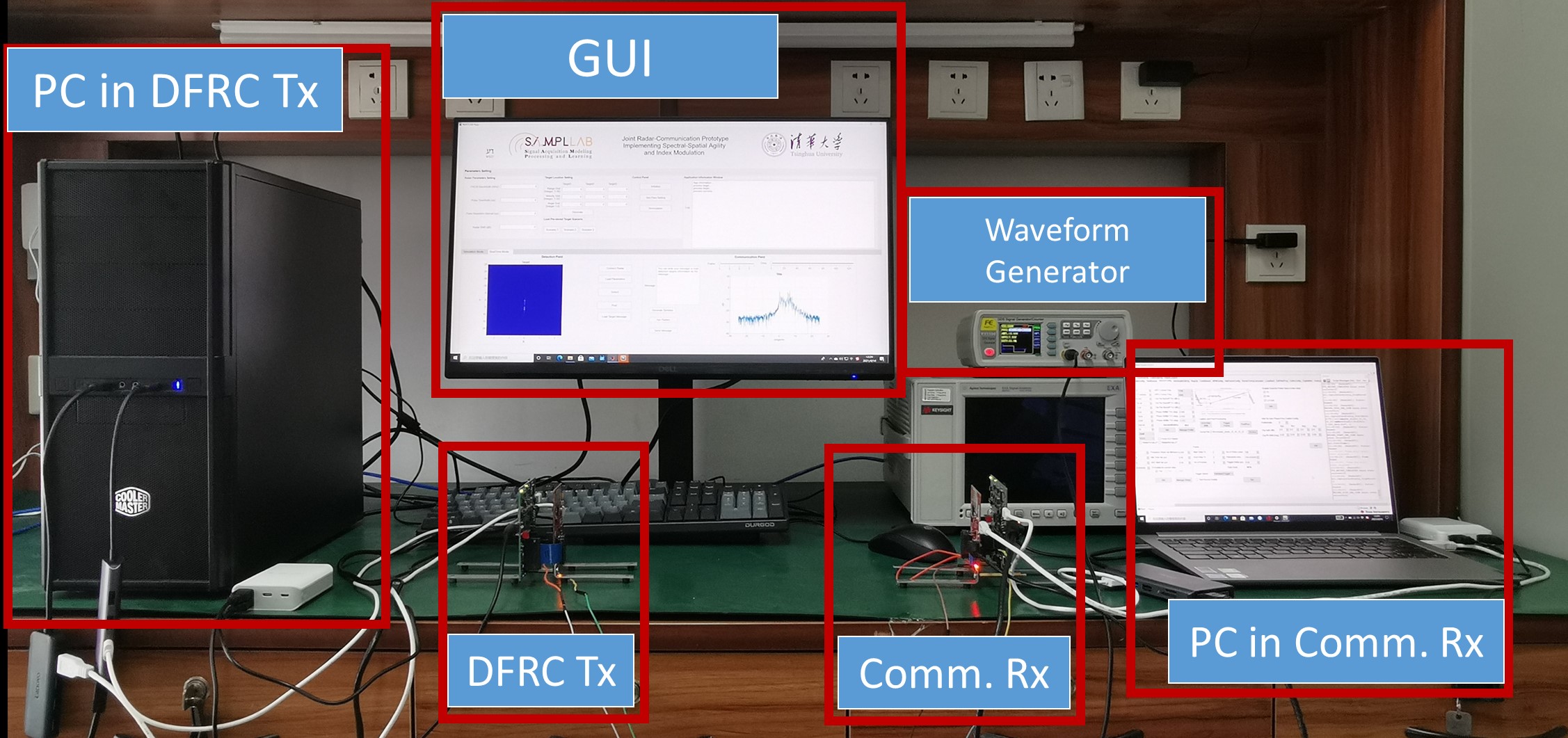
The architecture of this demo is depicted as below. It consists of 1) a PC server, which provides graphical user interface (GUI) for setting the DFRC parameters, generates the waveforms, and processes the received radar echoes (PC1); 2) a second PC server to detect the received message in the communications receiver (PC2); 3) a dual function radar and communication (DFRC) transmitter to transmit the DFRC waveforms; 4) a radar receiver to receive the radar echoes; 5) a communication receiver to receive the communication signals; 6) a waveform generator to synchronize the DFRC transmitter and the communication receiver. In particular, the DFRC transmitter and the radar receiver is implemented by the TI boards DCA1000 and AWR1843BOOST. Meanwhile the communication receiver is implemented by the TI boards DCA1000 and AWR1642BOOST.
Through the GUI, the parameters of the radar and communication subsystems are configured. Once the parameters are set and an experiment is launched, the DFRC waveforms are generated and transmitted by the DFRC transmitter. The communication information is embedded into the variations of the carrier frequencies of the transmit frequency modulated continuous waveforms (FMCWs). The radar echoes are received in the radar receiver and processed by the radar detection algorithm to recover the target scenario. The communication signal is received in the communication receiver, then processed to recover the transmitted message.
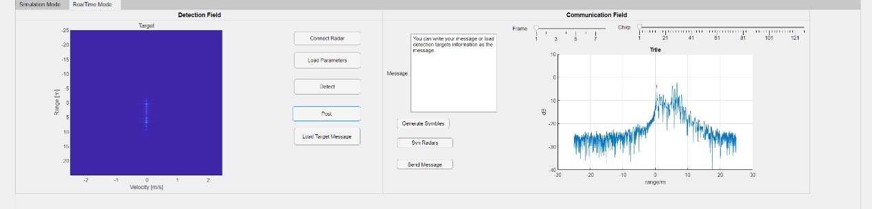
Results:
Two screenshots of the GUI are shown as below. The GUI shows the results of the simulation mode and the real-time mode. The configurable properties of the system include radar parameters, communication parameters and DFRC platform parameters. In the simulation mode, the communications bit error rate (BER) and the radar recovery result is simulated. In the real-time mode, the DFRC waveforms are transmitted to detect the nearby environments and convey the transmit message. It can be observed that the implemented demo is able to realize both radar and communication utilizing the low cost mmWave radar platforms. Therefore, it can provide an additional communications channel for vehicular applications, independent of the cellular network. Please refer to the demo movie and reference papers for more details.
Full-duplex DFRC Demo
Hardware Details:
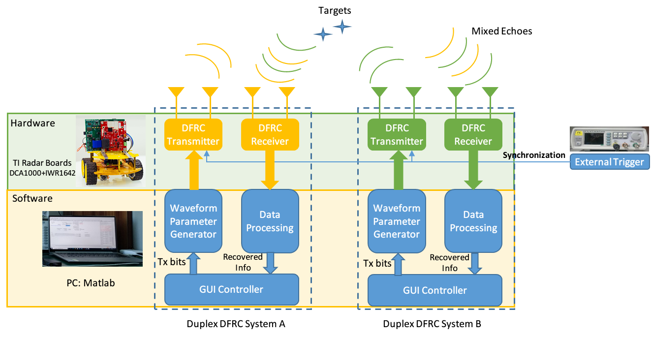
The hardware architecture and prototype are shown in the figure above. We implement two identical full-duplex DFRC prototypes to demonstrate the full-duplex communication. The whole system is composed of the following parts: (1) Graphical user interface (GUI) running on two separate PC servers to configure the radar parameters, generate waveforms, and process the received data. (2) Two identical DFRC transceivers implemented by TI boards DCA1000 and AWR1642BOOST. (3) A waveform generator to synchronize the two DFRC systems.
When the hardware prototype starts running, the DFRC transceivers are configured first. Then the communication messages are embedded into the selection of carrier frequencies and the selection of transmit antennas. The DFRC transceivers receive mixed echoes composed of self-radar signal and other users’ signal with information. Communication echo and self-radar echo occupy different spectral resources by designing appropriate subcarriers and antenna transmission modes, and thus target scenario and transmitted messages can be recovered respectively.
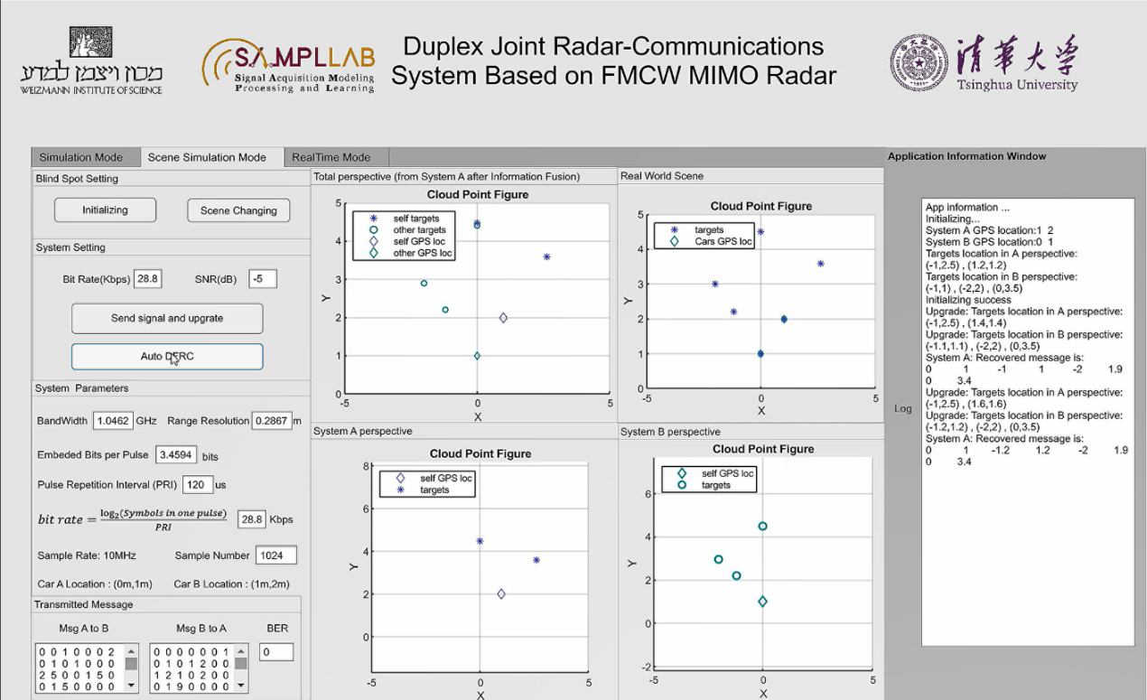
Results:
Two screenshots of the results are shown below, in simulation mode and real-time mode. In simulation mode, the duplex communication bit rate and the signal noise ratio (SNR) are configurable. The relative position of the two DFRC systems and the targets is simulated and shown in the middle figures. When the simulation starts running, the position of the target will automatically change, and the corresponding simulation results will be shown in real time, including radar range resolution, pulse repetition interval (PRI), communication bit rate, bit error rate (BER), and radar cloud point figure, etc. In real-time mode, two identical full-duplex DFRC prototypes send messages to each other and detect simultaneously. At a two-way communication bit rate of 28.8kbps for each user, the radar range resolution reaches 0.2m in laboratory tests. It proves that this system not only realizes both radar and communication functions, but also realizes high real-time full-duplex data transmission and blind spot information sharing. Please refer to the demo movie for more details.
SAJRC DEMO
Hardware Details:
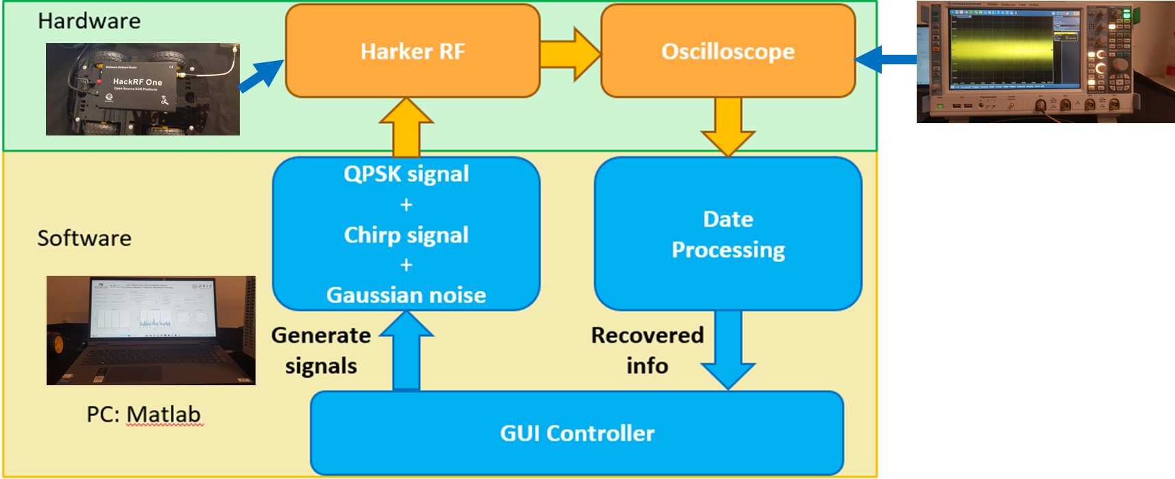
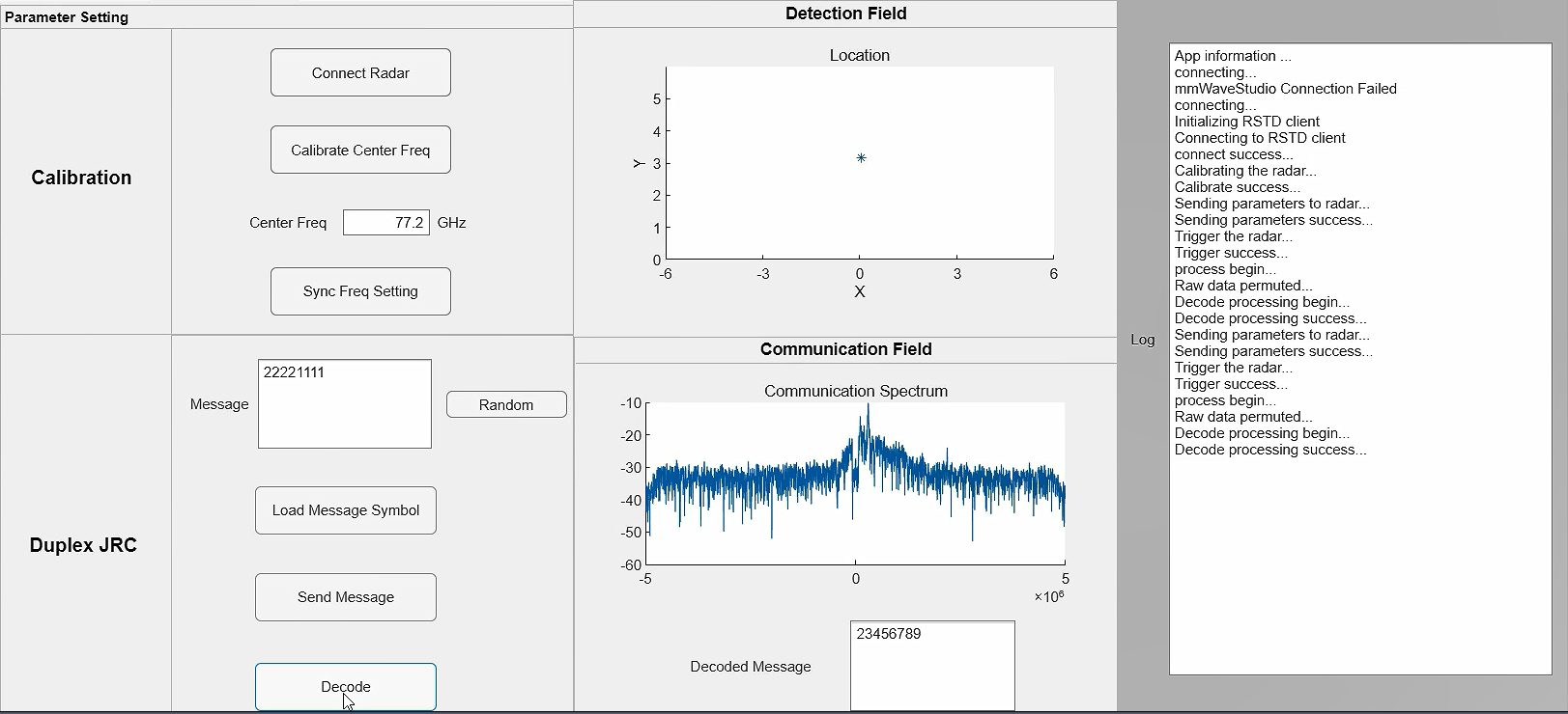
The hardware prototype of Single Antenna Joint Radar and Communication (SAJRC) is shown in the above figure. It consists of 1) a PC server, which provides a graphical user interface(GUI) for setting parameters of communication signals and radar echoes, generating combined waveforms, and processing received waveforms. 2) a HackRF One to transmit the combined signals. 3) an oscilloscope, which plays the role of a receiver to receive the combined signals.
Once the parameters are set by the GUI and the experiment is launched, the communication signals and radar signals are generated, combined, and sent to the HackRF One by the PC server, Then the HackRF One sends the combined signals to the oscilloscope through a line. The oscilloscope receives the signals, samples them, and uploads them to the PC server. The PC server utilizes a designed algorithm to decode the communication signals and detect the radar target.
Results:
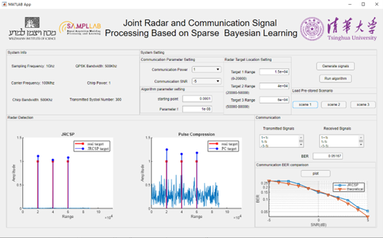
One screenshot of the results is shown above. The configurable properties of the system include communication parameters, radar parameters, and algorithm parameters. For communication signal decoding, the bit error rate (BER) is shown and compared with the theoretical limit under the white Gaussian noise channel. For radar detection, the result is compared with the pulse compression method. It can be observed that the implemented demo is able to separate two signals from the received combined signals. The communication BER approaches the theoretical limit and radar detection has improved robustness against the communication signal intensity.
References
- D. Ma, N. Shlezinger, T. Huang, Y. Shavit, M. Namer, Y. Liu, and Y. C. Eldar, "Spatial Modulation for Joint Radar-Communications Systems: Design, Analysis, and Hardware Prototype", IEEE Transactions on Vehicular Technology, Vol. 70, Issue 3, pp. 2283-2298, March 2021.
- T. Huang, N. Shlezinger, X. Xu, Y. Liu, and Y. C. Eldar, "MAJoRCom: A Dual-Function Radar Communication System Using Index Modulation", IEEE Transactions on Signal Processing, vol. 68, pp. 3423-3438, May 2020.
- D. Ma, N. Shlezinger, T. Huang, Y. Liu, and Y. C. Eldar, "Joint Radar-Communications Strategies for Autonomous Vehicles", IEEE Signal Processing Magazine, vol. 37, issue 4, pp. 85-97, July 2020.