
Time Encoding Machine
We develop the theory, algorithms, and board implementation of an asynchronous ADC for various classes of signals. Our proposed ADC does not require a global clock and instead samples the signal at irregular intervals determined by the times in which the integral of the signal passes a pre-determined threshold. This approach is referred to as IF-TEM (integrate and fire time encoding machine). Its main advantage is removing the global clock leading to power savings. Furthermore, we show that by encoding the input signal into a time sequence, the required number of bits to represent the signal is reduced while enabling robust signal reconstruction. We also show that for structured signals, the sampling rate can be below the Nyquist rate, and achieve the sub-Nyquist rates developed in the literature for synchronous sampling.
The operating mechanism of the IF-TEM, as shown in Fig. 1, utilizes an integrator to sum over the signal to be sampled and compare the result to a pre-determined threshold. When the threshold is reached, the sampler fires and records the time instant of the sampled point.
A notable application of IF-TEM arises in the context of Finite-rate-of-innovation (FRI) signals, have fewer degrees of freedom than the signal’s Nyquist rate, which enables sub-Nyquist sampling. As an example, consider an FRI signal consisting of a sum of L amplitude-scaled and time-delayed copies of a known pulse. Since the pulse is known, the signal is completely specified by L amplitudes and L time delays, which amounts to 2L degrees of freedom. In Fig. 2, we depict the implementation of IF-TEM specifically tailored for FRI signals, pre-processing and post-processing of the ADC. This results in less energy consumption in the ADC and allows for sub-Nyquist sampling.
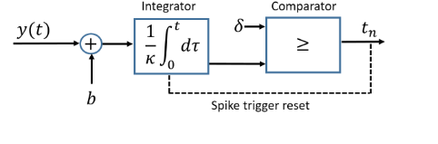
Figure 1: Time encoding machine with spike trigger reset. The input is biased by b, scaled by κ, and integrated. The difference between the time instances is recorded when the threshold δ is reached, after which the value of the integrator resets.
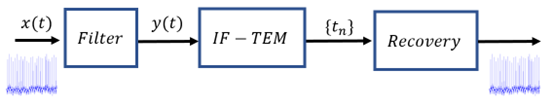
Figure 2: FRI signal x(t) is first filtered through a sampling kernel and then sampled using the IF-TEM, resulting in a set of time-instant differences. These differences are then used to calculate the time instances {tn}, from which the FRI signal is robustly reconstructed.
FRI-TEM hardware
working principle:
Our hardware components are designed to handle a wide range of FRI signal frequencies without requiring any modifications. Before the IF-TEM sampler is applied, a filter, also known as a sampling kernel, is employed to eliminate extraneous information from the signal and enable sub-Nyquist sampling. The IF-TEM hardware generates a set of time-instant differences each time the threshold is reached by sampling the filtered signal, and these differences are then used to calculate the time instances. To eliminate noise, we developed an integrator and a reset function to fully and quickly discharge the integrator's capacitor, which functions in its linear regime. Our robust reconstruction method demonstrates that FRI parameters can be accurately recovered using sub-Nyquist samples. Specifically, our system operates at a rate of eight times the rate of innovation, which is significantly less than the Nyquist rate of the signal. Fig. 3 showcases the IF-TEM hardware's operational output, utilizing real data.
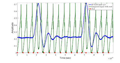
Figure 3: Our IF-TEM hardware sampling: the IF-TEM input signal y(t) (blue), the integrator output (green), and the IF-TEM time instances (red).
Board Specifications:
Our FRI-TEM hardware board is shown in Fig. 4. As illustrated in Fig. 5, our analog board consists of three sequential stages: the generation of an FRI signal, band-pass filtering, and an IF-TEM sampler. Using an analog approach, our FRI signal generator accurately simulates real-world applications such as radar and ultrasound. The signal production process involves a scope, splitter, analog delay generator, and a passive radio frequency (RF) combiner, producing an FRI pulse (10-500ns wide). The signal is then filtered using an eight-order 1MHz band-pass filter (BPF), which removes the zero frequency for robust reconstruction, providing a suitable trade-off between energy usage and reconstruction performance. The output of the filter is transmitted to the IF-TEM sampler, which includes the bias, integrator, comparator, differentiator, and reset function. To ensure sufficient samples for reconstruction, the δ threshold is manually regulated and adjustable using a potentiometer. The integrator obtains a signal that is always non-negative by adding the bias b to the input y(t).
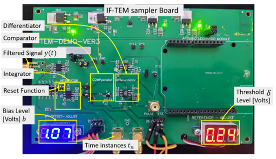
Figure 4: IF-TEM hardware board.
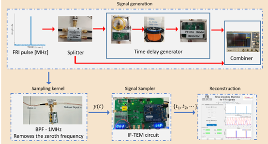
Figure 5: The FRI-TEM hardware prototype contains a signal generator, a sampling kernel, and an IF-TEM sampler. The generated signal is passed into a BPF of 1M Hz which removes the zero frequency for robustness. Finally, the resulting signal is sampled by an IF-TEM sampler board, and then the FRI signal is recovered.
Graphical User Interface:
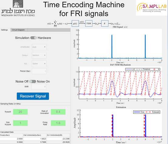 http:// https://www.weizmann.ac.il/math/yonina/green-data-acquisition
Hardware results:
The IF-TEM can efficiently reconstruct numerous FRI-Pulses configurations.
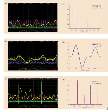
In each of these figures, the number of time instances produced is 19, 21, and 22, respectively, resulting in firing rates of 1.9 MHz, 2.1 MHz, and 2.2 MHz, which are all between 9.5 and 10.5 times the 20MHz Nyquist rate. The proposed hardware and reconstruction method retrieve the FRI parameters while operating at 10-12 times lower than the Nyquist rate with an SNR of up to -25dB.
ECG-TEM hardware
Our hardware components are designed specifically to handle ECG signals.
We have developed TEM hardware that enables efficient sub-Nyquist sampling and recovery of ECG signals, benefiting heart rate monitoring applications.
To facilitate sub-Nyquist sampling, a filter, also known as a sampling kernel, is applied before the IF-TEM sampler to eliminate extraneous information and enable efficient sampling. The IF-TEM hardware generates time-instant differences whenever the threshold is reached during the sampling of the filtered signal. These differences are then utilized to calculate the corresponding time instances. Our robust reconstruction method demonstrates the accurate recovery of ECG signals using sub-Nyquist samples. The ECG signal is filtered to remove its zeroth frequency, enhancing noise robustness. The processed filtered signal, denoted as y(t), is sampled using an IF-TEM sampler, resulting in a firing rate of 42-80Hz, approximately 1/20-1/40 of the Nyquist rate. Figure 6 showcases the operational output of the IF-TEM hardware, utilizing real data.
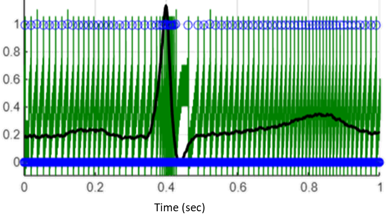
Figure 6: Our IF-TEM hardware sampling: the IF-TEM input signal y(t) (black), the integrator output (green), and the IF-TEM time instances (blue).
Board Specifications:
As shown in Fig. 7, our analog board comprises three consecutive stages: ECG signal generation, band-pass filtering, and an IF-TEM sampler. The ECG signal is initially passed through an eight-order 40Hz band-pass filter (BPF) to eliminate the zero frequency component, ensuring robust reconstruction while maintaining a balance between energy usage and reconstruction performance. The filtered signal is then directed to the IF-TEM sampler, which includes components such as bias, integrator, comparator, differentiator, and reset function. To guarantee an adequate number of samples for reconstruction, the δ threshold is chosen a priori and adjusted using a potentiometer. By adding the bias b to the input signal y(t), the integrator produces a non-negative signal at all times.
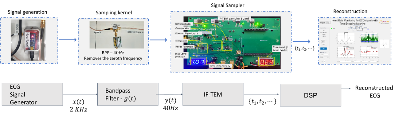
Figure 5: The ECG-TEM hardware prototype contains a signal generator, a sampling kernel and an IF-TEM sampler. The generated signal is passed into a BPF of 40 Hz which removes the zero frequency for robustness. Finally, the resulting signal is sampled by an IF-TEM sampler board, and then the ECG signal is recovered.
Graphical User Interface:
Hardware results:
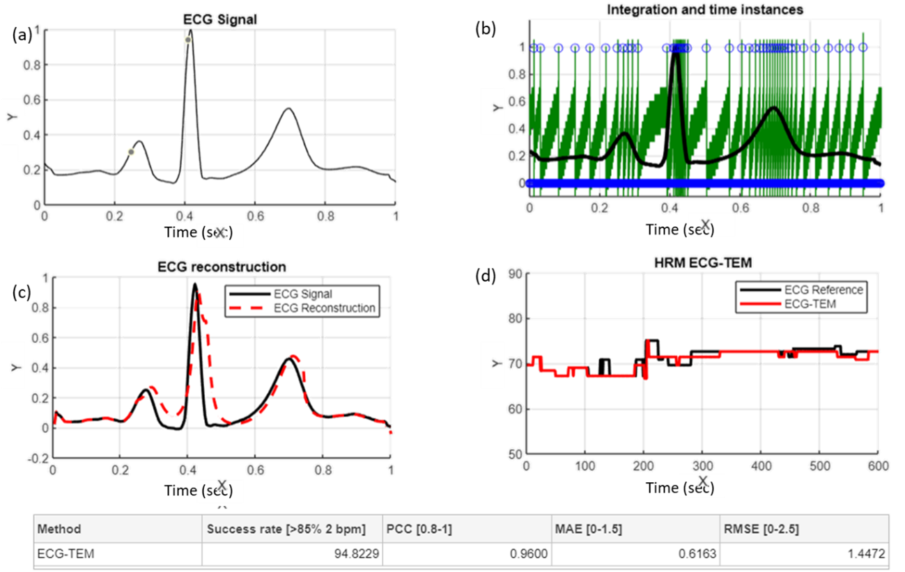
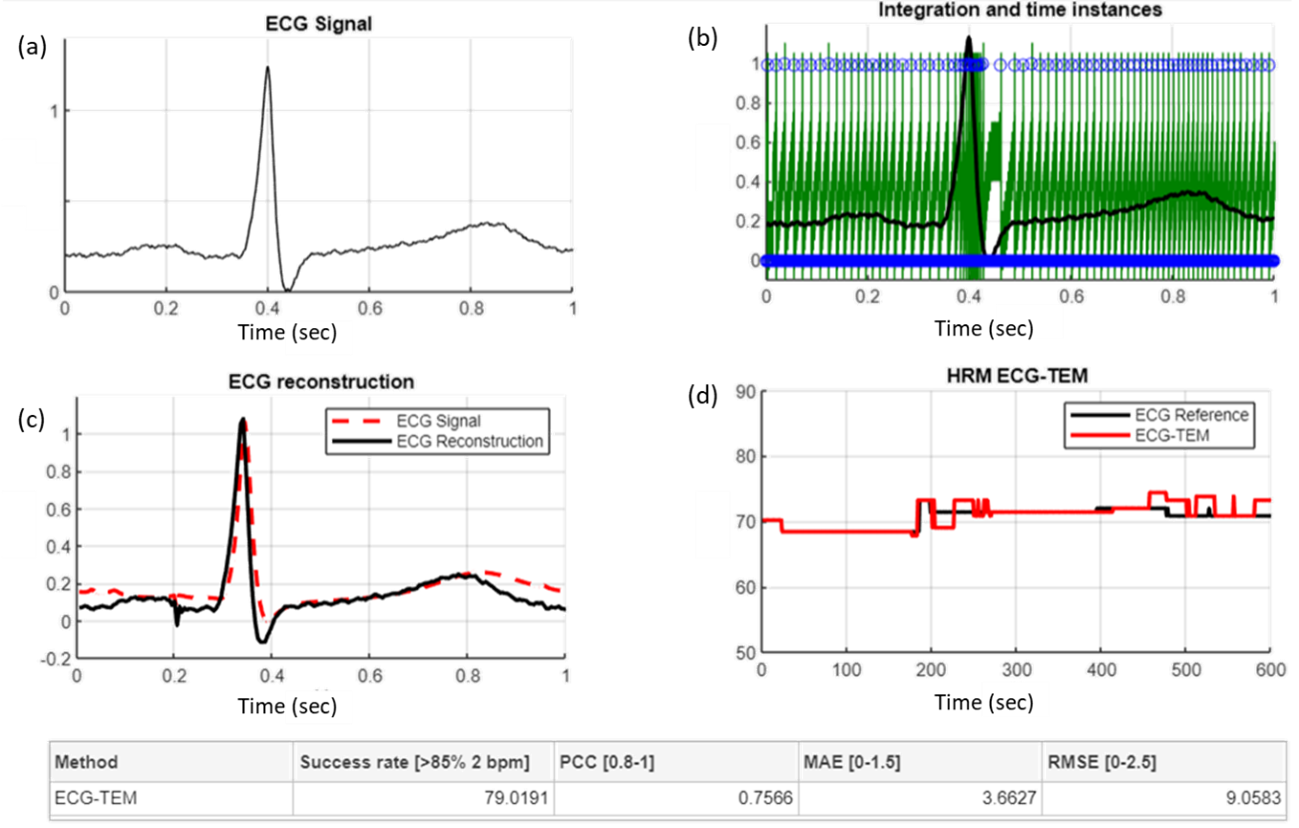
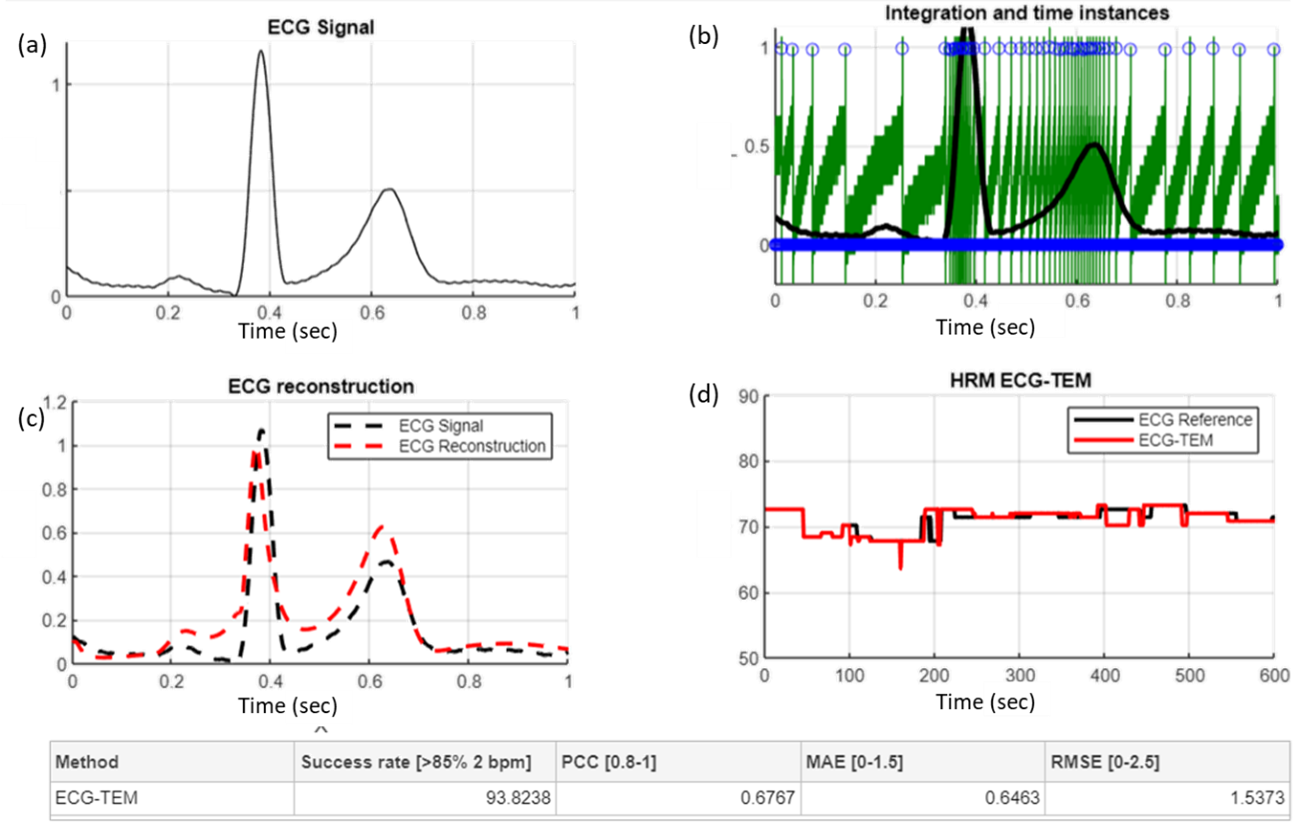
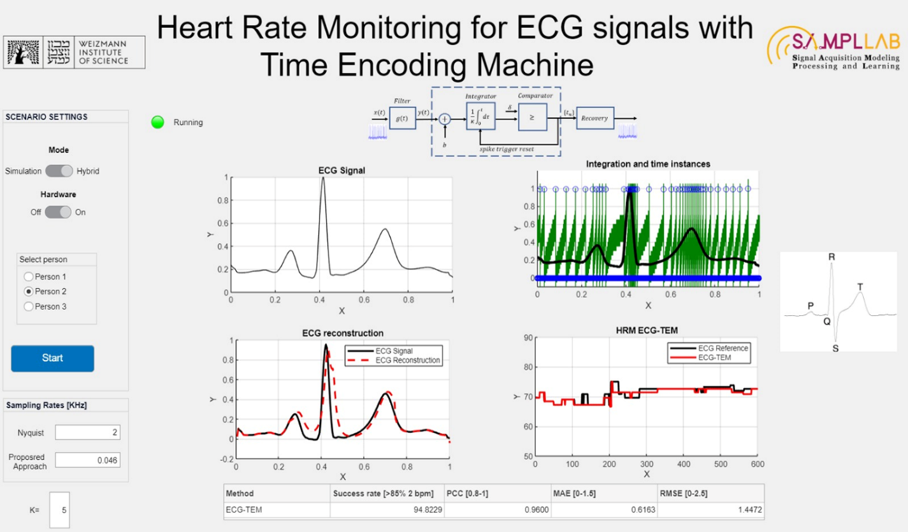
The IF-TEM can hardware enables efficient sub-Nyquist sampling and recovery of ECG signals, benefiting heart rate monitoring (HRM). The ECG reconstruction is utilized to conduct HRM, and compared to one calculated from a known synchronously sampled ECG at 2000 Hz. Specifically, we examined the resting scenario and compared the statistical metrics of the HR estimate with the reference output. To evaluate the quality of our estimates, we used the following statistical metrics: 1. Success rate, defined here as the percentage of time in which the HR estimate was different from the reference output by less than 2 beats per minute (b.p.m.), 2. Pearson Correlation Coefficient (PCC), 3. Mean-Absolute Error (MAE), and 4. RMSE. In each of the above figures, the number of time instances produced is 46, 70, and 49, respectively, resulting in firing rates of 0.046 KHz, 0.079 KHz, and 0.049 KHz, which are all between 20 and 40 times the 2KHz Nyquist rate. The proposed hardware and reconstruction method retrieve the ECG parameters while operating at 20-40 times lower than the Nyquist rate.
for more Green Data Acquisition: https://www.weizmann.ac.il/math/yonina/green-data-acquisition
References
[1] H. Naaman, N. Glazer, M. Namer, D. Bilik, S. Savariego and Y. C. Eldar, "Hardware Prototype of a Time-Encoding Sub-Nyquist ADC", Submitted to IEEE Transactions on Circuits and Systems, January 2023.
[2] H. Naaman, S. Mulleti and Y. C. Eldar, "FRI-TEM: Time Encoding Sampling of Finite-Rate-of-Innovation Signals," in IEEE Transactions on Signal Processing, vol. 70, pp. 2267-2279, 2022.
[3] H. Naaman, D. Bilik, S. Savariego, N. Glazer, M. Namer and Y. C. Eldar, "Sub-Nyquist TEM-Based Hardware for Heart Rate Monitoring of ECG Signals", ICASSP 2023.