The flux-to-voltage transfer function of SQUIDs is periodic in the applied flux Φa with a period of one flux quantum Φ0=h/2e and has “blind spots” which are regions of zero or low sensitivity. Using a SQUID at its highest sensitivity required, until recently, to flux bias the SQUID to its optimal working point, Φa≈Φ0/4.
Lithographically fabricated scanning SQUIDs are commonly used with a pick-up loop that scans close to the sample, rather than the SQUID itself. The SQUID, placed far from the sample, is inductively coupled to the pick-up loop. This setup allows adding flux to the remote SQUID without affecting the local field on the sample. The SQUID can thus be biased to Φ0/4 and operate at its highest sensitivity regardless of the local field on the sample.
The SOT, however, is designed to directly scan in very close proximity to the sample, allowing it to achieve high spin sensitivity and high resolution due to its small size. Flux biasing the SOT to Φ0/4 will be invasive, affecting the local field on the sample and is thus undesired. To heal the “blind-spots” problem we came up with an alternative to flux biasing the SQUID.
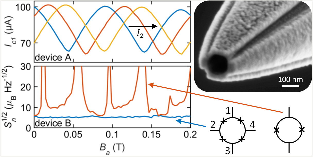
The solution is a novel multi-SOT (mSOT) device that includes four-terminals and four-junctions rather than two and two as in conventional SQUIDs. The extra degrees of freedom allow us to electrically in-situ control the interference pattern Ic=| cos(πΦa/Φ0 ) |, shifting it with respect to the applied flux. This allows optimal sensitivity at any value of the applied field, eliminating the blind-spots. The shift is induced by current biasing one or more extra terminals of the mSOT.
he current affects the phase drop φ of the superconducting order parameter along one of the extra Josephson junctions through its current-phase relation. The result is a high spin sensitivity, high resolution SOT that operate without blind spots.

- Top left: interference pattern shift induced by one of the control currents.
- Bottom left: electron spin sensitivity of the same mSOT device in two different setups: A. Upon setting both control currents to zero (red curve) the device acts as a two terminal SQUID showing blind spots (high values of spin sensitivity), and B. Adjusting the control currents to achieve optimal sensitivity at any given field (blue curve) eliminates the blind spots altogether.
- Top right: a scanning electron micrograph of an mSOT device.


