
Task-based Quantization
Handling High number of Analog Signals with small amount of Receivers
In this demo, we apply the task-based quantization method to a multi-user signal recovery problem and present a hardware prototype implementation which consists of a tailored configurable combining board, and a software-based processing and demonstration system. Through our experiments, we verify that with proper design, task-based quantization achieves a reduction of 25 fold in memory by reducing from 16 receivers with an ADC of 16 bits each to 2 receivers with 5 bits each, without compromising signal recovery performance.
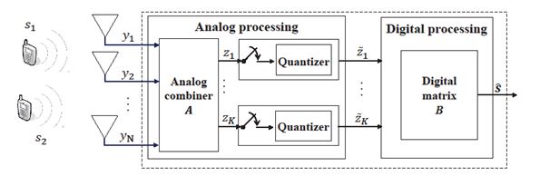
Fig. 1. Illustration of task-based quantization for multi-user signal recovery.
Compared with conventional high resolution quantizers, significant rate reduction can be expected by using low-bit quantizers. However, compensation for the distortion induced in quantization is required in subsequent digital processing, which results in complicated information extraction in the digital domain and an overall system performance degradation. To address these issues, the proposed task-based quantization takes into account the underlying task in the system design, and dramatically reduces the number of bits while allowing for accurate signal recovery. This is achieved by introducing an analog combiner, followed by joint optimization of the analog and digital processing and the bridge between them, i.e., the ADC. Task-based quantization may be applied to graph signal processing, channel estimation in massive MIMO communications, and target identification in radar.
- P. Li, N. Shlezinger, H. Zhang, B. Wang, and Y. C. Eldar, “Graph signal compression by joint quantization and sampling,” IEEE Transactions on Signal Processing, vol. 70, pp. 4512–4527, September 2022.
- N. Shlezinger; Y. C. Eldar, M. R. D. Rodrigues, "Hardware limited task based quantization", IEEE Transactions on Signal Processing, vol. 67 (20), pp. 5223–5238, August 2019.
- F. Xi, N. Shlezinger, and Y. C. Eldar, “BiLiMO: Bit-limited MIMO radar via task-based quantization", IEEE Trans. Signal Process., vol. 69, pp. 6267–6282, September 2021.
- Timur Zirtiloglu, Nir Shlezinger, Yonina C. Eldar, Rabia Tugce Yazicigil, ”Power-Efficient Hybrid MIMO Receiver with Task-Specific Beamforming using Low-Resolution ADCs”, 2022 IEEE International Conference on Acoustics, Speech and Signal Processing (ICASSP).
1. Task-Based Quantization Algorithm
A. System Model
Consider a single-cell network in which a base station (BS) is equipped with
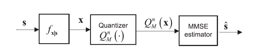
Conventional Quantization
The quantizer is used separately from the task recovery
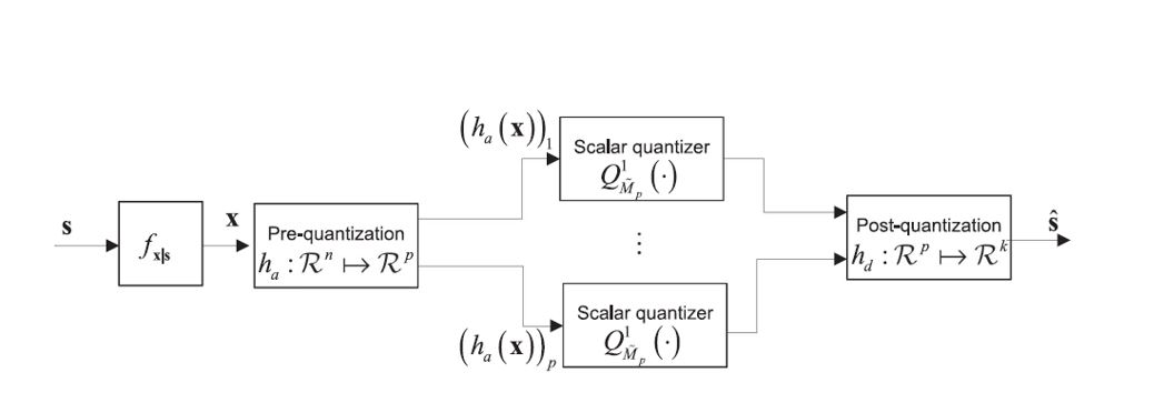
Task-based Quantization
The task information is utilized for the design of the overall system, including an analog combiner, scalar quantizers and digital part
Example
Consider a single-cell network in which a BS is equipped with N=16 antennas and serves K=2 single-antenna user terminals (UTs). Here our aim is to recover the signals of the two users based on task-based quantization, as shown in the following figure.
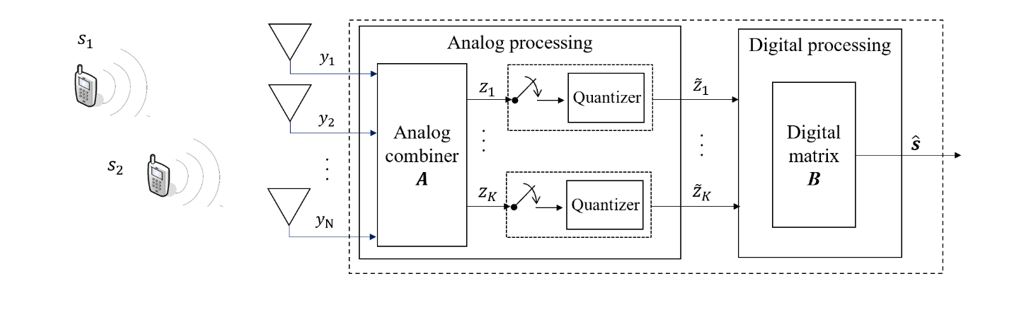
In this figure, s is the transmitted signals, y is the received signal which is given by
y = Hs + v
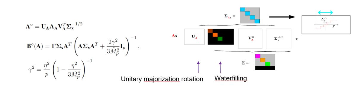
with H denoting the channel matrix and v the noise. Following the principle of task-based quantization, the received analog signal is first processed by an analog combiner A, followed by sampling and scalar quantization with limited quantization bits. Finally, the task is recovered by digital matrix B. The challenge is to jointly optimized the overall system according to the below objective.

The results are (details can be found in reference [1])
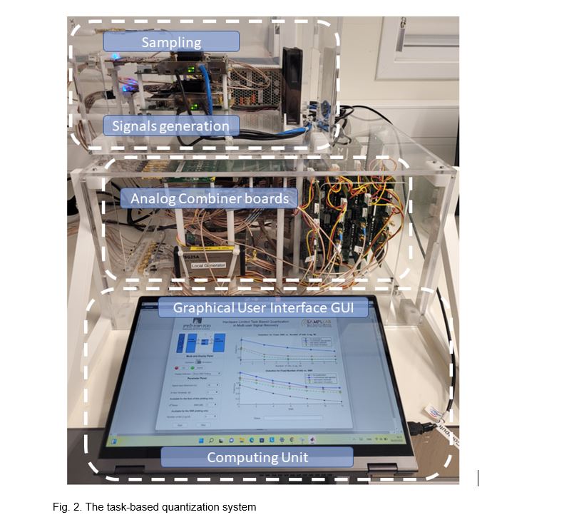
2. Hardware
Here, we apply task-based quantization to multi-user signal recovery and present a prototype, which consists of a hardware board and a software-aided demonstration system. In the considered setting, the system task is to recover multi-user transmitted signals, rather than the received signals on all antennas. Therefore, following the principle of task-based quantization, a tailored analog combiner board was built to properly pre-process the received signals prior to quantization. The outputs are then quantized by scalar quantizers with limited bits. Finally, the task vector is recovered by an optimized digital matrix. To visually demonstrate the above process, a MATLAB-based graphical user interface (GUI) was developed, which includes parameter controlling, data processing and results displaying. Experimental results illustrate the superiority of task-based quantization over the conventional task-ignorant one, mitigating the gap between the theory and its practical application.
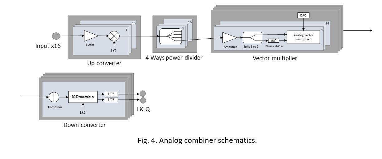
a) Board Specifications:
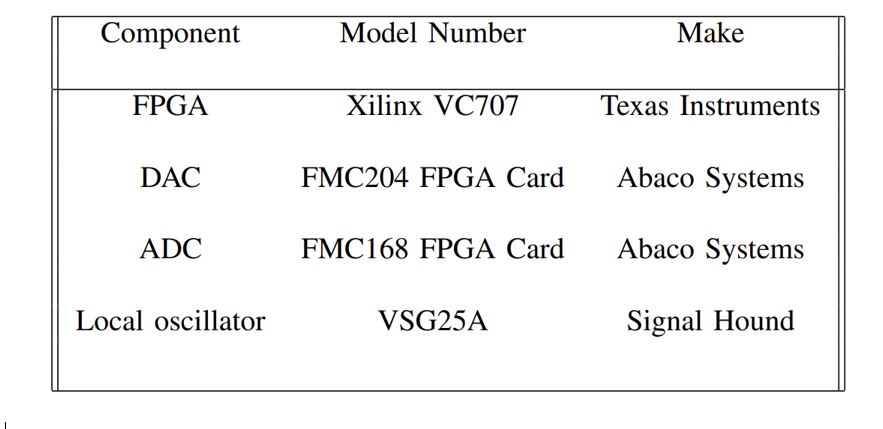
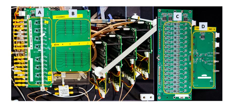
Fig. 3. The analog combiner hardware board
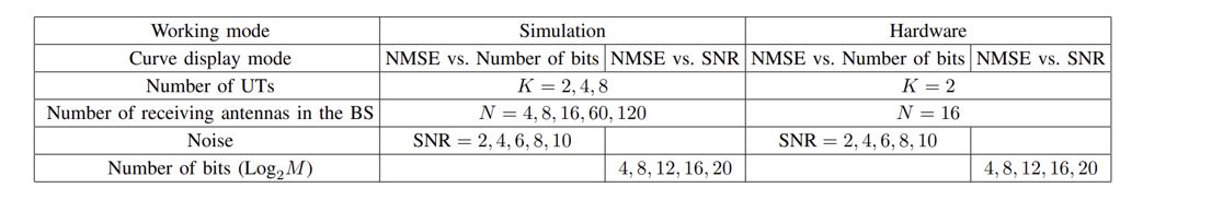
CONTROLLABLE PARAMETERS SUPPORTED BY GUI
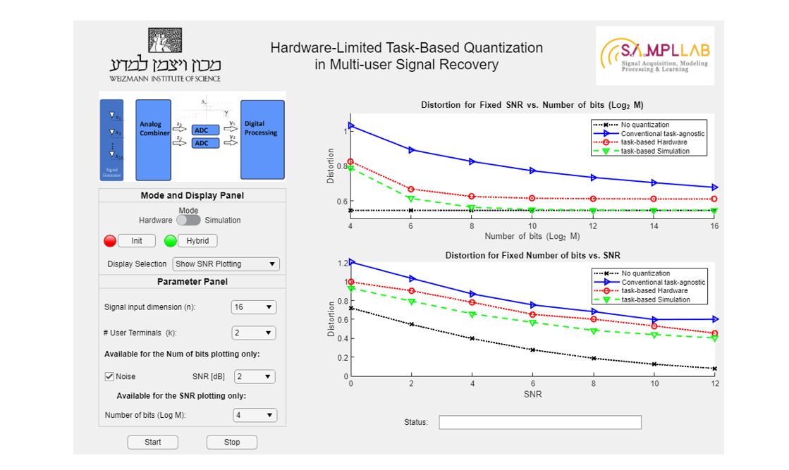
b) Graphical User Interface:
c) Hardware Results:
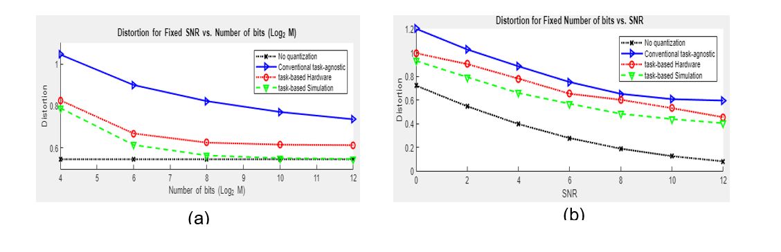
- Figs (a) and (b) show the MSE distortion with respect to different number of bits and SNRs, respectively.
- When each scalar quantizer uses at least five bits, i.e., "log" ("M" )"≥5K", the quantization error becomes negligible.
3. References
- N. Shlezinger, Y. C. Eldar, and M. R. D. Rodrigues, “Hardware-limited task-based quantization", IEEE Trans. Signal Process, vol. 67, no. 20, pp. 5223–5238, Oct. 2019.
- N. Shlezinger, Y. C. Eldar, and M. R. D. Rodrigues, “Asymptotic task- based quantization with application to massive MIMO", IEEE Trans. Signal Process, vol. 67, no. 15, pp. 3995–4012, Aug. 2019.
- X. Zhang, H. Zhang, N. Glazer, O. Cohen, E. Reznitskiy, S. Savariego, M. Namer and Y. C. Eldar, "Hardware Implementation of Task-based Quantization in Multi-user Signal Recovery", Arxiv, January 2023.
4. Videos
ICASSP 2022